A
Coaxial Magnetron Injection Gun
- recent experimental results and an improved gun design -
B. Piosczyk
Forschungszentrum Karlsruhe, Association EURATOM-FZK,
Institut für Hochleistungsimpuls- und Mikrowellentechnik, D-76021
Karlsruhe, Germany
e-mail: bernhard.piosczyk@ihm.fzk.de;
Tel.: + 49 7247 82 3541; Fax.: + 49 7247 82 4874
1. Introduction
Coaxial cavity
gyrotrons with an RF output power of 2 MW, CW, operated at 170 GHz are of
interest for the ITER tokamak. Development work performed at the Forschungszentrum
Karlsruhe has demonstrated the feasibility of manufacturing such a gyrotron and
information necessary for a technical design has been obtained. As part of the
development detailed investigations have been performed on problems related to
the coaxial arrangement [1,2]. Experiments have been performed on a coaxial
gyrotron operated in the TE31,17 mode at 165 GHz. This gyrotron
is of demountable type with no sweeping of the electron beam along the
collector surface. The power density at the collector limits the maximum
achievable pulse length.
2. Recent experimental observations
When
the pulse length was extended for the first time over about 10 ms a fast
jump of the current Iins to the insert was observed. Iins
rose from a value in the mA range up to very large values
(> 20 A), limited only by the external circuit. The jump of Iins
occurred independently of the value of the beam current Ib. Even at
Ib £ 1 A it has been observed
when the pulse length was extended to about 30 ms. Finally, the coaxial
insert was damaged by the related power loading. In detailed investigations it
has been found that the effect is due to the build up of a Penning discharge in
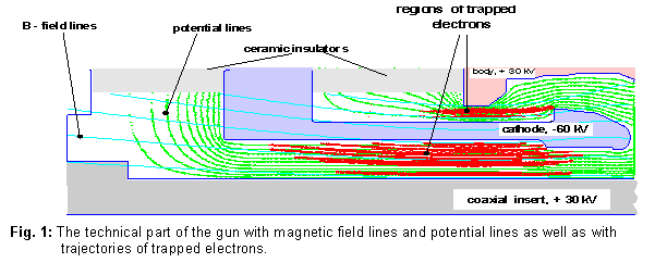
the rear part of the electron gun. In the cylindrically symmetric part between
the coaxial insert and the cathode an electron trap is created by the
electrostatic and magnetic fields as shown in Fig. 1. Thus a Penning type
discharge may build up. In agreement with numerical simulations electrons from
this discharge may diffuse along the magnetic flux surfaces towards the coaxial
insert as observed experimentally. In order to verify the hypothesis of the
Penning discharge, the geometry of the cathode and the insert has been modified
such that trapping of electrons should not occur. Experiments performed with
the modified geometry showed no limitation due to the above described effect.
At Ib » 50 A a maximum pulse length
of 22 ms has been achieved with an RF-output power of about 1 MW. At
this current the pulse limitation is due to the temperature rise of the
collector surface by about 6000C. At reduced beam currents the pulse
length has been up to above 100 ms without problems. This confirms the
given explanation and the suggested method of suppression.
After having
suppressed the build up of a Penning discharge, the origin of the body current
Ibody has been investigated. Both the current to the insert, Iins
and the current to the outer wall contribute to Ibody. In the
measurements it has been found that (1) Ibody is dominated by Iins
with a negligible contribution of the current to the outer wall: Ibody » Iins,
and (2) the value of Iins increases approximately linearly with the
positive body voltage Ubody which is applied to the anode, the
gyrotron body and the coaxial insert (Fig. 2). The collector is kept at
ground potential. At operation without depressed potential (Ubody
= 0 kV) Iins is only about 2 mA and rises to about
35 mA at Ubody = 27 kV as shown in Fig. 2.
Furthermore the value of Iins increases with time and becomes
stationary after about 5 to 7 ms. The values given in Fig. 2
correspond to the stationary values. The background pressure has been measured
to be between 10-8 and few times 10-7 mbar
depending on current and pulse length. At the end of longer pulses with a
strong pressure rise an additional increase of Iins has been
observed before a voltage breakdown.
To explain this
behavior the following mechanism is suggested. 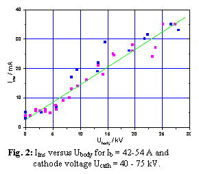 By
applying a body voltage a negative potential barrier arises in front of the
collector. Thus electrons created by ionization of the background gas become
trapped axially between the negative cathode and collector potential and
radially by the strong axially symmetric magnetic field. Low energy electrons
generated by ionizing the background gas are only able to escape either by
radial diffusion or by diffusion in velocity space. In case of operation with Ubody = 0 kV
these electrons may drift along the magnetic field lines towards the collector.
The current to the insert is assumed to be mainly due to diffusion of the
trapped electrons across the magnetic field. For beam electrons with an energy
around 90 keV the ionization has been estimated to be only about 10-6
if the path is 1.5 m at a pressure of 10-7 mbar. This
means that at Ib = 50 A an equivalent electron current
of only about 50 mA is generated by ionization. For Ubody » 27 kV
the measured value of Iins is about 1000 times higher,
however. In order to be able to explain this an additional ionization of
the background gas due to the trapped electrons oscillating between the cathode
and the collector is suggested. Under stationary conditions which are
established after a few ms the electron rate generated by ionization has to be
in equilibrium with Iins. This means that along the beam path a
background plasma is created in which an electron current is oscillating
between the cathode and the collector. In the investigated case the amount of
the trapped and oscillating electron current must be significantly larger than
Ib. Whether the residual charge of the plasma is positive (necessary
for compensation of the beam space charge [3]) or negative should depend on the
balance between the ionization rate, the ion drain current towards the cathode
and collector and the diffusion rate of electrons. As a summary, it follows that
in operation with depressed collector a significantly more dense plasma along
the beam path may be created. More detailed investigations are needed to
understand the consequences on gyrotron operation.
By
applying a body voltage a negative potential barrier arises in front of the
collector. Thus electrons created by ionization of the background gas become
trapped axially between the negative cathode and collector potential and
radially by the strong axially symmetric magnetic field. Low energy electrons
generated by ionizing the background gas are only able to escape either by
radial diffusion or by diffusion in velocity space. In case of operation with Ubody = 0 kV
these electrons may drift along the magnetic field lines towards the collector.
The current to the insert is assumed to be mainly due to diffusion of the
trapped electrons across the magnetic field. For beam electrons with an energy
around 90 keV the ionization has been estimated to be only about 10-6
if the path is 1.5 m at a pressure of 10-7 mbar. This
means that at Ib = 50 A an equivalent electron current
of only about 50 mA is generated by ionization. For Ubody » 27 kV
the measured value of Iins is about 1000 times higher,
however. In order to be able to explain this an additional ionization of
the background gas due to the trapped electrons oscillating between the cathode
and the collector is suggested. Under stationary conditions which are
established after a few ms the electron rate generated by ionization has to be
in equilibrium with Iins. This means that along the beam path a
background plasma is created in which an electron current is oscillating
between the cathode and the collector. In the investigated case the amount of
the trapped and oscillating electron current must be significantly larger than
Ib. Whether the residual charge of the plasma is positive (necessary
for compensation of the beam space charge [3]) or negative should depend on the
balance between the ionization rate, the ion drain current towards the cathode
and collector and the diffusion rate of electrons. As a summary, it follows that
in operation with depressed collector a significantly more dense plasma along
the beam path may be created. More detailed investigations are needed to
understand the consequences on gyrotron operation.
3. Improved design of a coaxial magnetron injection gin (CMIG)
Based on the
results concerning the build up of a Penning discharge due to trapping of
electrons, a new CMIG gun has been designed. By conical shaping of the insert
and the corresponding part of the cathode, electron trapping has been avoided.
The gun will be fabricated for use in a 2 MW, 170 GHz coaxial gyrotron
operated in the TE34,19 mode.
References:
[1] B.
Piosczyk et al., "Coaxial cavity gyrotron - recent experimental
results", IEEE Trans.
Plasma Science, vol. 30, 2002,
819-827.
[2] B.
Piosczyk, “A novel 4.5 MW electron gun for a coaxial gyrotron” IEEE Trans. Electron
Devices, vol. 48, 2001, 2938-2944.
[3] G.
Dammertz et al., "Long-pulse operation of a 0.5 MW TE10,4
gyrotron at 140 GHz",
vol. 24, 1996, 570-578.