Development of Frequency Step Tunable 1 MW
Gyrotrons in D-Band
M. Thumm1,3), A. Arnold3), E. Borie1), G. Dammertz1), O. Drumm1), R. Heidinger2),
M.V. Kartikeyan1), K. Koppenburg1), A. Meier2), B. Piosczyk1), D. Wagner4), X. Yang1)
Forschungszentrum Karlsruhe, Ass. EURATOM-FZK, 1)IHM, 2)IMF I,
76021 Karlsruhe,
Germany
3)Universitaet Karlsruhe, IHE, 76128 Karlsruhe, Germany
4)Max-Planck-Institut
fuer Plasmaphysik, Ass. EURATOM-IPP, Boltzmannstr. 2,
85748 Garching, Germany
E-mail: manfred.thumm@ihm.fzk.de, Phone: ++49 7247 822440, Fax: ++49 7247 824874
Introduction
The availability of MW gyrotrons with fast frequency
step tunability (several GHz/s, tuning in 2-3 GHz steps for approximately 10
different frequencies) permits the use of a simple fixed, non-steerable mirror
antenna for local electron cyclotron plasma heating and current drive (EC
H&CD) and plasma stabilization in thermonuclear fusion research.
Successful
gyrotron experiments at FZK Karlsruhe employing a 140 GHz, TE22,6-mode
cavity, a quasi-optical (QO) mode converter with dimple-type launcher, a
broadband silicon nitride composite Brewster angle window and a single-stage
depressed collector (SDC) gave up to 1.6 MW output power (pulse duration: 1-5 ms)
at efficiencies between 48 and 60% for the entire operating mode series in the
frequency range from 114 to 166 GHz (TEm,5 with
m = 18 to 22, TEm,6 with m = 20 to 26 and TEm,7 with m =
22 to 26) [1]. Frequency
tuning in steps of approximately 3.7 GHz was achieved by slow variation (in
minutes) of the magnetic field strength in the cavity. Recently, similar
results have been achieved at IAP Nizhny Novgorod employing a 140 GHz, TE22,8-mode
cavity in 50 ms-pulse operation [2].
The FZK gyrotron
was also investigated with respect to fast tunability (in seconds) [3]. For
that purpose, the tube was operated in a special hybrid magnet system
consisting of the superconducting magnet in the cryostat and additional normal
conducting (NC) magnets at cavity and gun, with a fast switching time constant.
Problems due to the magnetic coupling between the different magnets were solved
by using a current control system for the NC-magnets. Finally, step-tuning
operation between five modes from 132.6 GHz (TE20,6) to 147.4 GHz
(TE24,6) at MW power levels in time steps of 1 s was achieved
[3].
The different
operating modes have approximately the same radius of the electric field
maximum (caustic) in the cavity and must have the same sense of rotation so
that the coupling to the electron beam is comparably good and the pattern and
direction of the mm-wave output beam are very similar [1]. Special broadband quasi-optical output
couplers for different modes and different frequencies have to be employed. Other
challenges in the development of such frequency tunable gyrotrons are the
proper electron gun and the SDC operating in varying magnetic field.
1 MW, 105-140
GHz, 10 s Gyrotron
A
new EC H&CD system is under development for the ASDEX-Upgrade tokamak
at IPP Garching [4]. Four
1 MW gyrotrons with SDC will generate 4 MW power with a pulse duration of
10 s. The first gyrotron is being built at GYCOM-N and can work at 140 GHz (TE22,10)
and 104 GHz (TE18,7), making use of the resonances of the
conventional CVD-
diamond vacuum window at these frequencies. A second step-tunable gyrotron is designed to work at
several frequencies within the same interval (TE17,6 mode at 105 GHz
and TE22,8 at 140 GHz). A CVD-diamond output window mounted at the
Brewster angle will allow broadband transmission. The diameter of the synthetic
diamond disk for this window will be 120-140 mm. The QO mode
converter and the window unit have been developed in collaboration between FZK
Karlsruhe and IAP Nizhny Novgorod.
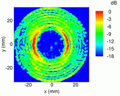
 A new QO mode
generator for low power tests has been designed and fabricated. Here a Gaussian
beam is focused onto a mode specific caustic through the translucent wall of a
coaxial cavity. First measurements of the output field pattern showed a very
good performance at most of the gyrotron output frequencies (e.g. Fig. 1).
Since all operating modes of a step-tunable gyrotron have a similar structure,
with their caustic radius being approximately half the cavity radius, only one
set of resonator and lenses is required. Only a minor readjustment of the QO
components is needed for
A new QO mode
generator for low power tests has been designed and fabricated. Here a Gaussian
beam is focused onto a mode specific caustic through the translucent wall of a
coaxial cavity. First measurements of the output field pattern showed a very
good performance at most of the gyrotron output frequencies (e.g. Fig. 1).
Since all operating modes of a step-tunable gyrotron have a similar structure,
with their caustic radius being approximately half the cavity radius, only one
set of resonator and lenses is required. Only a minor readjustment of the QO
components is needed for 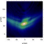 generation of
different modes.
generation of
different modes.
 The QO mode
converter of the gyrotron consists of a dimpled-wall antenna (Denisov-type
launcher) and a beam forming mirror system optimized for nine modes from TE17,6 to TE23,8 [5].
For these modes the dimpled-wall antenna shows a well focused beam with low
diffraction losses (Fig. 2). The first mirror is a large quasi-elliptical one,
the second and third are phase correcting mirrors with a non-quadratic shape of
the surface. These two mirrors were also optimized for broadband operation in
the various design modes.
The QO mode
converter of the gyrotron consists of a dimpled-wall antenna (Denisov-type
launcher) and a beam forming mirror system optimized for nine modes from TE17,6 to TE23,8 [5].
For these modes the dimpled-wall antenna shows a well focused beam with low
diffraction losses (Fig. 2). The first mirror is a large quasi-elliptical one,
the second and third are phase correcting mirrors with a non-quadratic shape of
the surface. These two mirrors were also optimized for broadband operation in
the various design modes.
First
measurements on a 1.923 mm thick, 120 mm diameter chemical vapor deposition
(CVD)-diamond disk showed a homogeneous distribution of the loss tangent in an
elliptic area, which can be used for the Brewster angle window. The measured values of the complete disk
are between about 2 x 10⁻⁵ and 8 x 10⁻⁵. The median of
the loss tangent is
3.6 x 10⁻⁵. Due to the ellipitical shape of the Brewster window only
the best area of the disk will be used. A 140 mm diameter disk for a full-size
diamond Brewster angle window is being developed at Element Six (formerly
DeBeers Industrial Diamonds).
[1]
M. Thumm, et al., Fus. Eng. and Design 53 (2001)
407-421.
[2]
V.E.
Zapevalov, et al., Proc. 27th Int. Conf. on IRMMW, San Diego, USA,
2002, pp. 1-2.
[3]
K.
Koppenburg, et al., IEEE Trans. on Electron Dev. 48 (2001) 101-107.
[4]
F. Leuterer,
et al., 22nd Symp. on Fusion Techn. (SOFT), Helsinki, 2002, paper C17.
[5]
E. Borie et
al., IEEE Trans. on Plasma Science 30 (2002) 828-834.