Introduction
The first two-frequency gyrotron Odissey-1 has been
installed and put into operation in the new multi-frequency ECRH system at the
ASDEX Upgrade tokamak experiment. It works at 105GHz and 140GHz with output
power 610kW and 820kW respectively for a pulse length of 10s. A further
extension of the system with 3 more gyrotrons is underway. These gyrotrons will
be step-tunable and operate at two additional intermediate frequencies between
105 and 140GHz. The variable frequency will significantly extend the operating
range of the ECRH system, e.g. allow for central heating at different magnetic
fields. Other experimental features, like the suppression of neoclassical
tearing modes (NTM), require to drive current on the high field side without
changing the magnetic field. The stabilization of NTM’s requires a very
localized power deposition such that its center can be feedback controlled, for
instance to keep it on a resonant q-surface. For this reason fast movable
launchers have been installed.
Gyrotron Operation
The two-frequency GYCOM gyrotron
Odissey-1 has a single-stage depressed collector. Therefore the beam voltage
can be limited to a maximum value of 60kV. The maximum beam current is 40A. The
operating modes are TE17,6 at 105 GHz and TE22,8 at 140
GHz. Here we make use of the 3l/2 and 4l/2 resonances (l is the wavelength) of the
single-disk synthetic diamond vacuum window at these frequencies. The frequency
can be changed between two ASDEX Upgrade pulses and requires an adjustment of
the cryomagnetic field, the gun magnetic and the collector magnetic fields. Reliable
operation was achieved, only limited by the available high power long-pulse
load. Two modulation schemes have been tested with this gyrotron. A 100% power
modulation with frequencies up to 1kHz was achieved by switching both, cathode
and body voltage on and off. Higher modulation frequencies up to 25 kHz with a
modulation depth up to 90% were achieved by a reduction of only the cathode
voltage from 42kV to 25kV while keeping the body voltage constant. First plasma
test shots were performed with a maximum power of 820kW at 140 GHz and a pulse
length up to 0.8s. The total measured frequency variation during a gyrotron
pulse was 140 MHz. Out of this, a drift
of ~100MHz happened in the first 100ms of the pulse and repeatedly during
modulation (Fig.1), very likely due to space charge effects. The remaining
shift of 40MHz to steady state results from the thermal expansion of the
cavity. The freezing of the inner gyrotron cooling circuits, caused by a magnet
failure, led to a deformation of the cavity of Odissey-1. The gyrotron was
returned to GYCOM for repair and will be replaced by the next two-frequency
series tube Odissey-2. After repair, Odissey-1 will be equipped with an
improved quasi-optical mode converter to further reduce the stray radiation in
the tube. A tunable double-disc window will be mounted allowing the operation
of Odissey-1 as a step-tunable gyrotron.
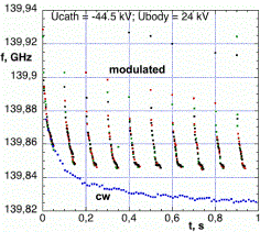
Fig.1: Measured frequency
drift of gyrotron Odissey-1 during a modulated and a cw 140 GHz pulse.
Matching Optics Unit and Transmission
Line
Since the phase distribution
and the azimuthal angle of the gyrotron output beam are different at different
frequencies, a special pair of phase correcting mirrors is required for each
frequency. The mirrors are mounted on turntables in the Matching Optics Unit
(MOU) and automatically put into place when the frequency and therefore the
operating mode changes. The transmission to the torus is in normal air, through
corrugated aluminum waveguides with I.D.=87mm over a total length of about 70m.
Since most part of the waveguide path is straight, the number of miter bends could
be limited to 7 and 8 respectively. Calorimetric measurements in the MOU and at
the end of the transmission line, next to the torus window, gave a total
transmission loss of only 12% at 105GHz and 10% at 140GHz. A fast steerable
launcher enables to steer the beam over the whole plasma cross section. In
order to cope with thermal load, disruption forces and mechanical dynamics, the
mirror is made out of copper-plated graphite. The toroidal angle can be varied
between shots by rotating the launcher around its axis. A fast drive is used to
control the poloidal launching angle during a discharge. The design goal of
10°/100ms was achieved during the tests.
References
[1] Leuterer F., et al., Fus. Eng. Des. 53 (2001) 277
[2] Thumm M., et al., Fus. Eng. Des. 53 (2001) 407
[3] Zapevalov V., et
al., Radiopysics and Quantum Electronics
47 (2004) 396